|
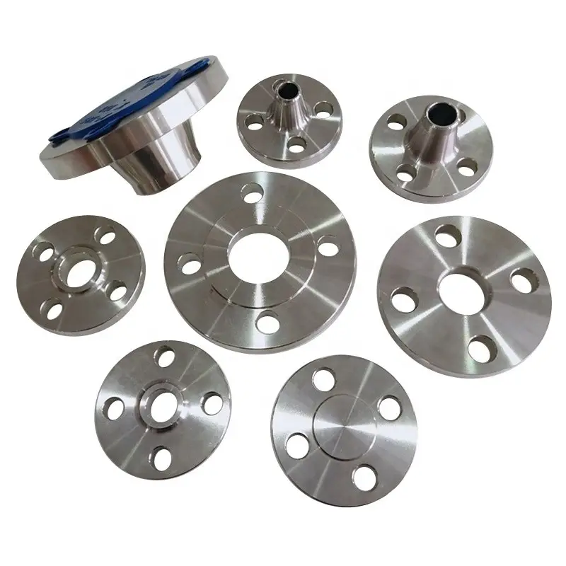
Designator |
Material |
Bar Stock |
Forged |
|
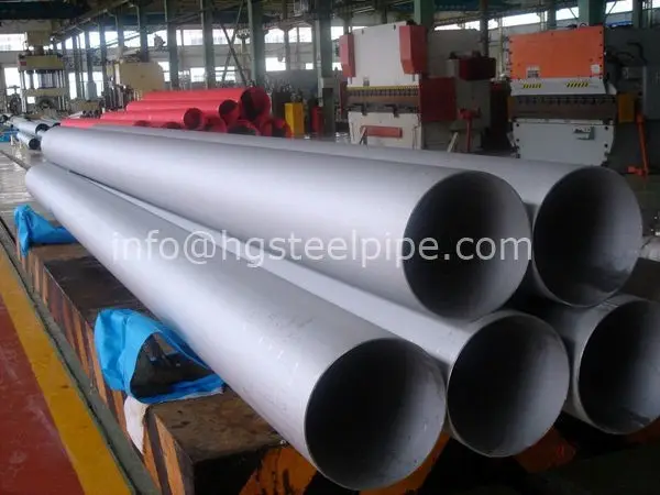
SS |
Stainless Steel 316 |
ASTM A276 |
ASTM A182 |
|
S4 |
Stainless Steel 304 |
ASTM A276 |
ASTM A182 |
|
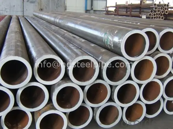
CS |
Cabon Steel |
ASTM A108 |
ASTM A105 |
|
B |
Brass |
ASTM B16/B453 |
ASTM B283 |
|
AL |
Aluminum |
ASTM B211 |
ASTM B247 |
Plating and Coating
To resist corrosion, all carbon steel fittings are treated with an electrodeposited zinc plating.
Thread Specifications
|
Thread Type |
Specification |
|
NPT |
ASME B1.20.1, SAE AS71051 |
|
ISO/BSP (parallel, based on DIN 3852) RP and RS fittings |
ISO 228, JIS B0202 |
|
ISO/BSP (tapered, based on DIN 3852) RT fittings |
ISO 7/1, BS EN 10226-1, JIS B0203 |
|
ISO/BSP (gauge) (based on EN 837-1 and 837-3) RG fittings |
ISO 228, JIS B0202 |
|
Unified (SAE) ST fittings |
ASME B1.1 |
Temperature Ratings
|
Fitting Materials |
|
Gasket, O-Ring Materials |
|||
|
Material |
Max Temperature |
Material |
Max Temperature |
Mini Temperature |
|
|
stainless steel |
1000 °F / 537 °C |
Buna N |
230 °F / 110 °C |
– 13 °F / -25 °C |
|
|
Carbon steel |
375 °F / 190 °C |
Fluorocarbon FKM |
400°F / 204 °C |
–20°F / -28 °C |
|
|
Brass |
400 °F / 204 °C |
Copper |
400°F / 204 °C |
–325°F / -198 °C |
|
For proper assembly following assembly instruction shall be followed. Improper assembly may lead to malfunctions or impair safety.
Assembly in fittingbody
1. Cut the tube:
1/2˚ angle tolerance to the tube axis is permissible. Tube cutter is not recommendable.
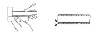
2. Lightly remove chips and particles from the inside and outside cut edges of tube. Bevel up to 0.2mm × 45˚ is permissible.
3. For tube bend, the minimum height from the straight pipe end to the bending radius must be at least twice the height of the nut.
4. Lubricate thread and cone of the fitting body, ring and thread of nut.
Assembly
5. Slip nut and then ring onto the tube end. Ensure that the ring is placed correctly.
6. Screw nut manually onto fitting body until finger tight. Hold the tube against the shoulder in the cone of the fitting body.
7. Mark nut and tube for measuring the prescribed turns of the nut.
8. Tighten the nut 1 1/4 turns. Tube must not turn with tube. Stop edge of the ring limits over-tightening by increasing tightening torque.
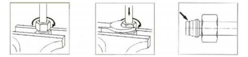
Check & Final Assembly
9. Loosen nut and remove ring-mounted tube from fitting. And check if a visivle collar has formed on the pipe in front of the first cutting edge. If not, tighten slightly more.
10. Insert the pre-assembled tube into the fitting.
While holding fitting body with a wrench, tighten nut approx. 1/4 revolution beyond the point of a clearly perceptible resistance.